
Device cannot power on
There are two possible causes for an Xbox One X power failure: a problem with the power supply or the motherboard.
Diagnostic Steps
First, check if the power supply is outputting 12V. If there is no 12V, it may be due to a power supply failure or a short circuit on the motherboard preventing the power supply from generating 12V.
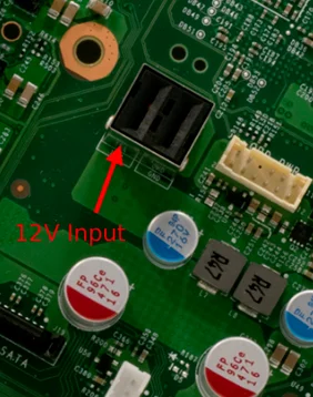
If there is 12V, the next thing to check is whether there is a 5V backup power supply.
If there is 5V, the next thing to check is the 1.1V, 3V, and 1.8V power lines.
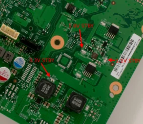
If these voltages are all backup voltages, the problem likely lies with the southbridge integrated circuit.
If 3.3V is missing, it might be due to a faulty U54 IC. Check for short circuits around this IC and confirm the 1.8VSTBY is present. The U54 IC cannot power on without 1.8V.
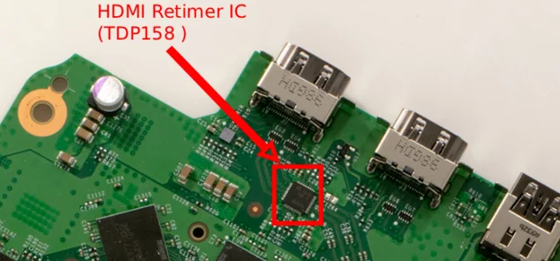
A common problem is 2.4V on the 3.3V line and 0.44V on the 1.8V line, caused by the HDMI timer IC. You can remove it from the motherboard to test; the computer will power on and then power off without the timer.
If there is no 12V voltage, disconnect the power supply from diode mode and measure the positive terminal of the motherboard power supply. The reading should be between 0.400 and 0.500. If so, replace the power supply.
If the reading is 0.000, the 12V line is short-circuited.
If there is no 5V voltage on the motherboard, it is very likely because this line is short-circuited. Switch the multimeter to diode mode again, measure the line, and check if the voltage is high. Short circuits in random capacitors are common in this line. If a capacitor is short-circuited, it is recommended to refer to the circuit diagram to find the replacement value.
If there is no 3.3V STBY, replace the U54 IC (TPS56C215).
If the 3.3V and 1.8V lines are even lower, it is expected that the Retimr IC U29 (TDP158) should be replaced.
To replace these chips, follow the steps below:
Replacing the Chip
Desoldering the Old Chip:
Heat the chip from above using a hot air gun or soldering iron. Heat for a few seconds until the factory solder begins to melt.
Gently push away the debris with tweezers. If it moves, it’s ready to be lifted.
While the motherboard is still warm, clean the old solder from the motherboard pads with solder and a soldering iron.
Prepare the motherboard and new chip:
Apply a thin layer of new solder to the cleaned motherboard pads. Avoid over-soldering, especially the center square.
Pre-solder the new chip’s pads with a small amount of solder to ensure good contact.
Solder the new chip:
Align the new chip with the motherboard. Align the dots on the chip with the small triangle markings on the motherboard for proper positioning.
Heat the chip from above using a hot air gun. Observe whether the solder melts; this can be judged by slight chip movement.
Gently touch the chip with tweezers to allow surface tension to stabilize it. Avoid using excessive force.
Inspection and cleaning:
Inspect all connections with a microscope. Ensure there are no solder bridges between the pins.
If any connection appears problematic, gently touch the affected pad with a soldering iron, resolder, and correct.
After assembling the console, ensure all functions are working properly.
If you replaced the Retimer IC, ensure the host can output 4K images.

