

The device does not power on when the power button is used.
Power LED remains off.
Both screens are off.
No sound.
One or more component malfunctions may cause this problem. Symptoms may vary slightly depending on which part is faulty. Compare your device to the table below to identify the most likely cause of the malfunction. All tests are assumed to be performed using a known good battery. This table only applies to cases using a good battery.
Symptom Action
Can charge, but cannot power on.
Check the power button/slider.
Can charge, but cannot power on. The green light flashes for one second when attempting to power on.
Check the screen cable and WiFi module connection. If either is missing, the startup test will fail.
Check the F2 fuse.
Check for a faulty WiFi module.
Cannot charge or power on.
Check if the F1 and F2 fuses are connected.
Check the continuity of the EM10 near the charging port.
Check the power connector.
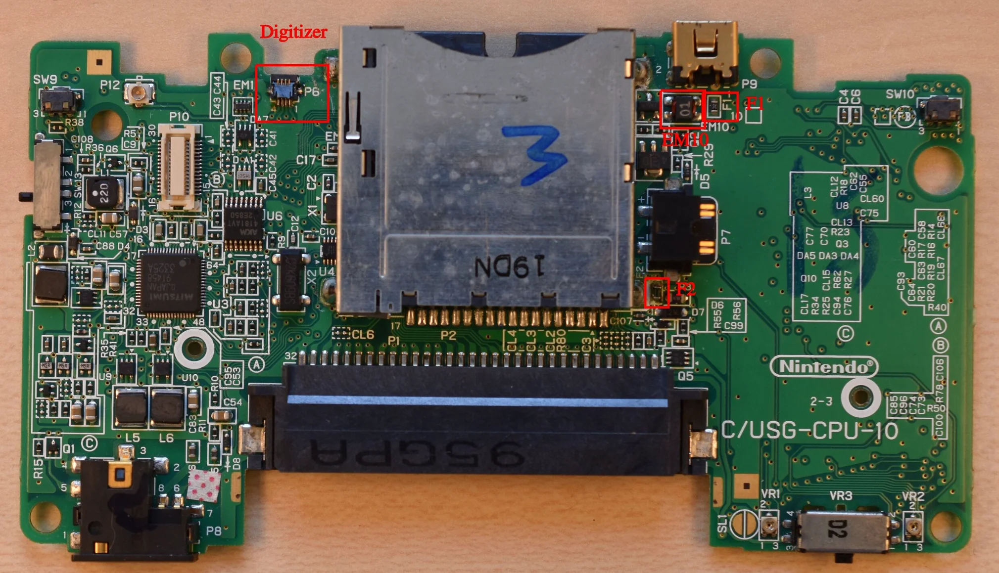
Check the Power Button/Slider
The power button is located on the bottom of the PCB, labeled SW13.
The switch has 4 pins. Measure the following dimensions without using the button:
Pin 2 to Pin 3 – Short
Pin 1 to Pin 2/3 – Open
Pin 1 to Pin 4 – Open
Pin 4 to Pin 2/3 – Open
If you press the power button, pin 1 should now be shorted to pins 2 and 3. If not, the power button is faulty. To ensure a correct diagnosis, connect both screens and the WiFi module using known good parts, connect a fully charged battery (polarity!), and then use tweezers to short pin 1 of the power button to pins 2 and 3. If the device powers on, that’s the only problem. Continue by replacing the power switch.
Check Screen Cables and WiFi Module Connections
Ensure all cables are plugged in straight and not at an angle. All screens must be fully connected. Ensure the WiFi module is connected. The WiFi antenna is not needed when the device is powered on. Then connect a charging battery (polarity!), and use the power button, or short-circuit pins 1 through 2 and 3 of the power button (if the power button is faulty). If the device powers on, that’s the problem.
Check Fuse F2
Fuse F2 is located near the power connector and near the DS game slot pins on the bottom of the PCB. Check the continuity of this fuse with a multimeter. If it’s damaged (measures high resistance), continue by replacing F1/F2.
Check for a faulty WiFi module
There are two ways to check:
Check the WiFi module by testing it on a known good device. If the device powers on, the WiFi module is fine. If not, replace the WiFi module.
Check the device by testing it with a known good WiFi module. If the device powers on, the WiFi module is faulty. If it remains off, the WiFi module may be fine, but we can’t be sure unless we test it on another device or the same device.
Check Fuse F1
Fuse F1 is located next to the power connector and EM10. Check the continuity of this fuse with a multimeter. If it’s faulty (measured as high resistance), proceed to replace F1/F2.
Check EM10. EM10 is located next to the charging port and F1. Check for continuity. The pins parallel to the charging port should be connected. See Figure 2. If there is no continuity between these pins, or between them and other pins, proceed with a replacement EM10.
Check the power connector. Visually inspect the power connector. If any bent pins or other damage are found, replace the connector. Plug in a known good USB power cable. Measure the continuity of the cable to the power connector pins. If the connector fails the test, proceed to replace the power connector.
Replace the power switch. Remove the defective power switch. Solder a new power switch.
Replace F1/F2. Remove the broken fuse and clean the pads. Don’t just remove the fuse and plug in the wires, as this could cause further damage if it’s not the only problem with the device. Replace with a suitable fuse. When purchasing a fuse, ensure the current rating is the same as the original (0.5A, unverified!) and the size is 0603.
Replacing the EM10: Remove the EM10 filter and replace it with a new one. If you don’t have one, or to test if the problem is resolved, you can bridge the pins that should be connected. Note that doing so will make your device more susceptible to the instability of cheap, low-quality power supplies.
Replacing the Power Connector: Remove the 6 pins of the power connector from the top of the PCB and disconnect the broken power connector. After removing the solder, clean the pads to allow for resoldering of the new power connector.

